Alessandro Acuna
Structural Engineer
Mechanical Engineer passionate about aerospace and advanced manufacturing, specialized in developing structural components from concept to advanced FEM validation. Focus on composite materials, CAD, FEA, and explicit simulations.
Availability
Currently at Airbus (contract until Dec 2025). Open to a new Structural Engineer role from January 2026.
Madrid, Spain · DE IT ES UK
Key competencies
Experience

AIRBUS - Structural Design & Analysis Engineer Madrid, ES
- Development and assessment of repair solutions for composite and metallic components.
- Part design for A350 HTP and Section 19 (rear fuselage) in CATIA V5.
- Design Office interface in production, ensuring structural integrity and compliance.
- Development of numerical models and explicit simulations for composite damage mechanisms.

DLR - Master Thesis · R&D Engineer Stuttgart, DE
- Thesis for the EU project r-LightBioCom on sustainable high-performance composites for automotive/aerospace.
- Computed environmental footprint for 1 kg of materials in openLCA.
- Quasi-static & dynamic compression tests on cores (honeycomb/foam) and KPIs combining LCA and mechanical performance.
- Implementation and calibration of LS-DYNA MAT cards from test data.
- FEM static/dynamic analyses to validate experiments.

UniBo Motorsport - Stress & Design Engineer Bologna, IT
- Design and Stress Analysis of automotive parts (monocoque moulds, dashboard support, driver harness).
- FEM on CFRP chassis under multiple loads; investigation of delamination causes.

D.V.P. Vacuum Technology - Bachelor Thesis · R&D Engineer Bologna, IT
- Experimental campaigns on flow rates and pressure losses in turbines and control valves.
- Built performance maps in GT-Suite and validated the model.

CPC Group - Composite Laminator Modena, IT
- Lamination of CFRP moulds and a chassis for Formula SAE team.
Academic Projects
Composite stiffened panels
Buckling & damage tolerance checks, layup optimization (skin & stringers), deflection verification. UPM · Feb–May 2025
Composite laminate — Hashin (Abaqus)
UD laminate under tension vs compression; ply-by-ply failure using Hashin initiation; FEM-driven analysis. UPM · Jan–Mar 2025
Rear Fuselage — Section 19 (Skin & Stringers)
Skin laminate & stringer concept, drop-offs, reinforcements, frame joints (clips, Ø4.8 mm). UPM · Jan–Mar 2024
Motorbike rear subframe — AlSi10Mg (SLM)
Topology optimization, VDI 2230 bolted joints, static/fatigue validation (Ansys), weight minimization. Unibo · Sep–Dec 2024
Composite drone structure
Lamination definition, thickness optimization, harmonic & impact FEM analyses. Unibo · Feb–Jun 2023
Composite stiffened panels
Objective — Design and validate CFRP panels with stringers, minimizing weight while meeting buckling and damage-tolerance requirements under the defined load cases.
What I did
- Defined layups for skin and stringers (symmetry, balance, ply percentages).
- Pre-sized reinforcements and verified local/global buckling and stringer crippling.
- Checked deflections and margins of safety (MS) vs requirements.
- Performed thickness optimization (weight vs stiffness/stability) with FEM feedback.
- Used buckling mode shapes to guide redesign iterations.
Tools
Abaqus / Ansys for FEM; engineering spreadsheets for trade-offs; aerospace laminate rules.
Results
- Weight reduction: ≈ X–Y% (replace with your actual value).
- MS ≥ 0 for buckling and crippling on critical load cases.
- Deflections ≤ specified limit.


- Buckling & Crippling
- Optimized Layup
- FEM-Driven
- MS ≥ 0
Composite laminate — Hashin (Abaqus)
Objective — Simulate a UD laminate under tension and compression using Hashin damage initiation to identify ply-by-ply failure and compare tensile vs compressive capacity.
Model
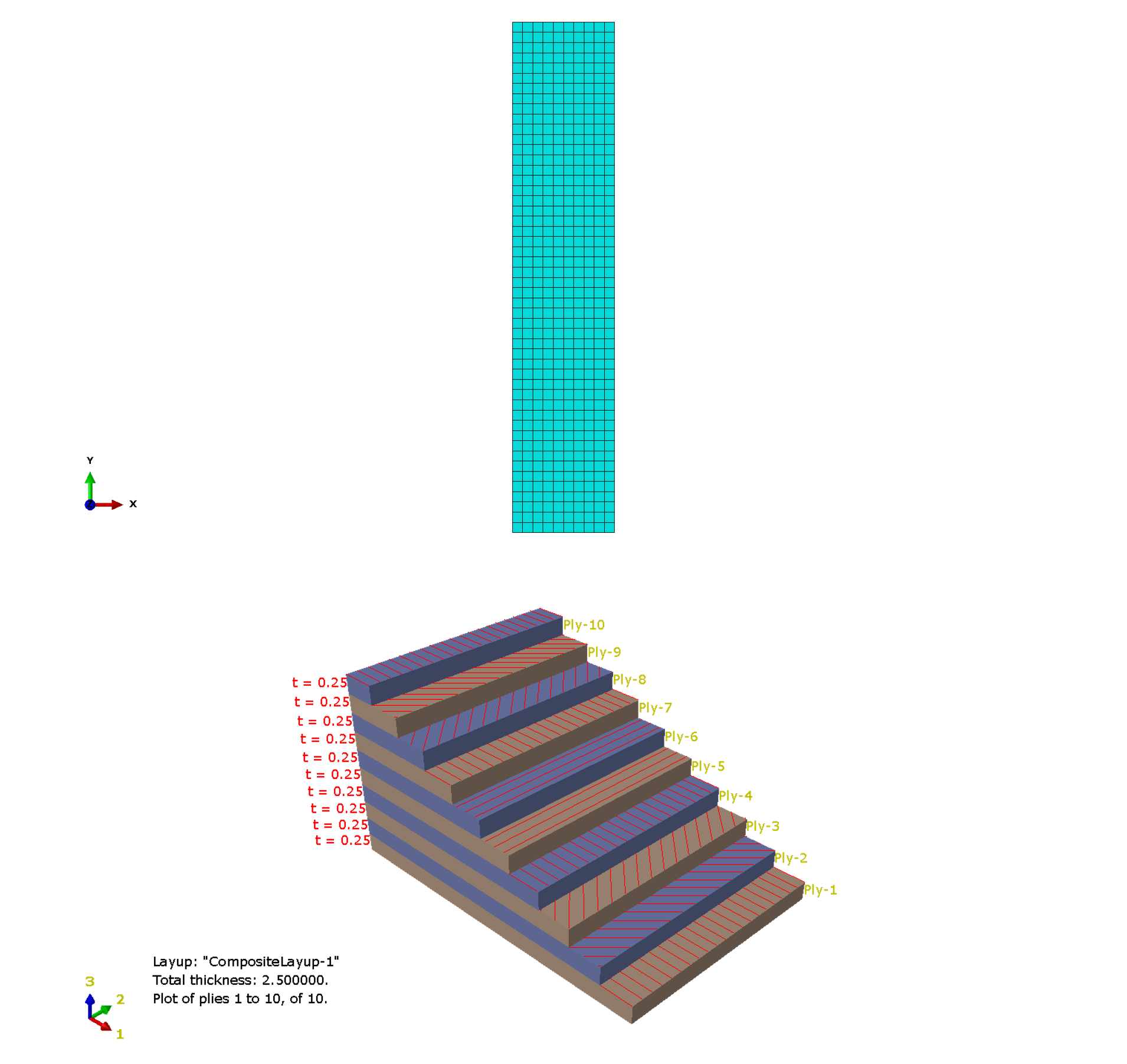
- Coupon: 100 × 20 mm, 10 plies × 0.25 mm = 2.5 mm; symmetric layup [0°, ±45°, 0°, 90°]s.
- Elements: S4R shell mesh (~2 mm); material: UD lamina with elastic + Hashin inputs.
- BC/Load: bottom clamped; top edge coupled to a Reference Point with prescribed Y-displacement.
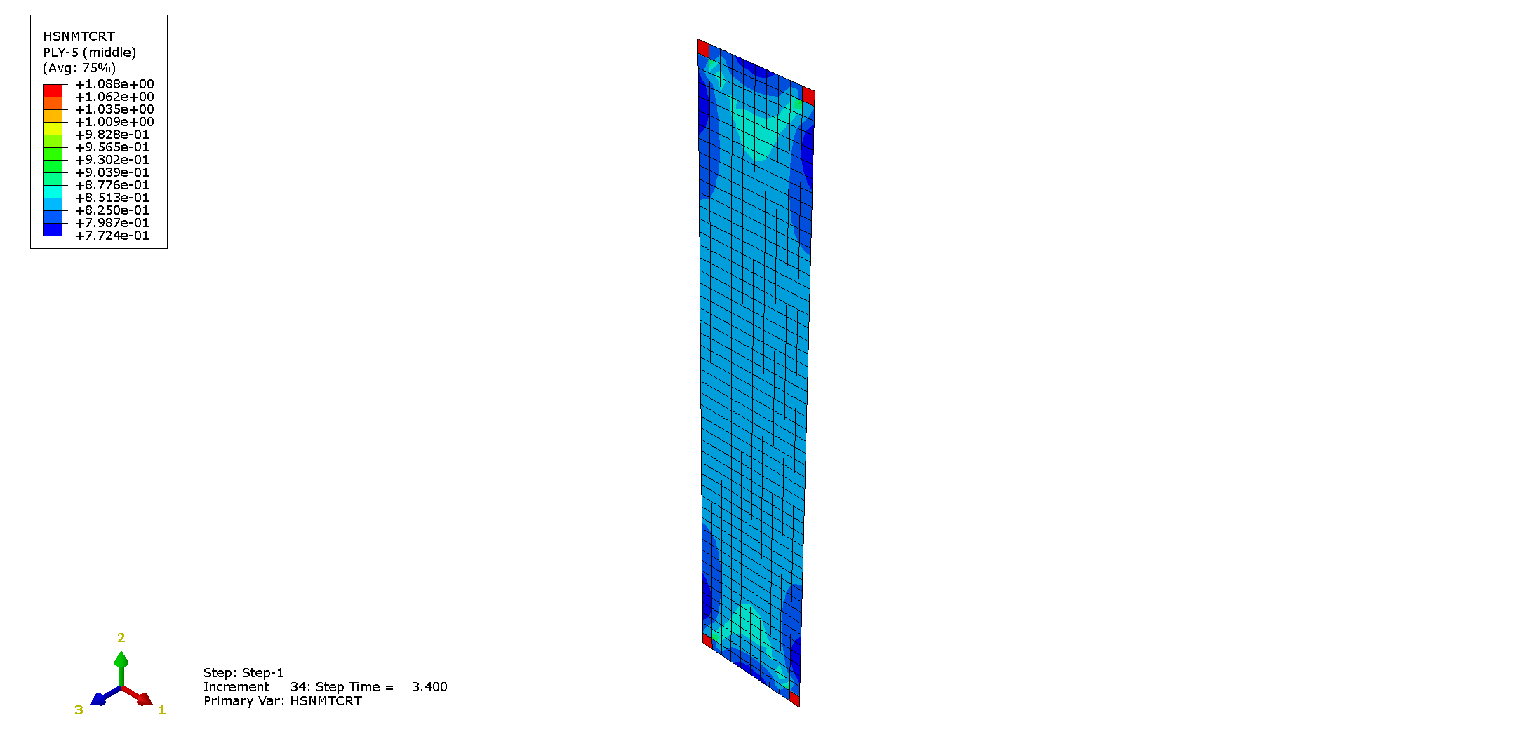
- Damage model: Hashin initiation (no damage evolution). Outputs: HSNFTCRT, HSNFCCRT, HSNMTCRT, HSNMCCRT.
Results
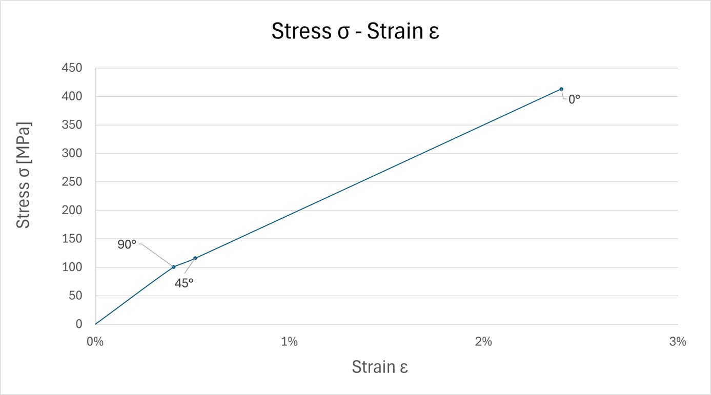
- Tension: 90° matrix-tension → ±45° matrix-shear → 0° fiber-tension; UTS ≈ 413 MPa.
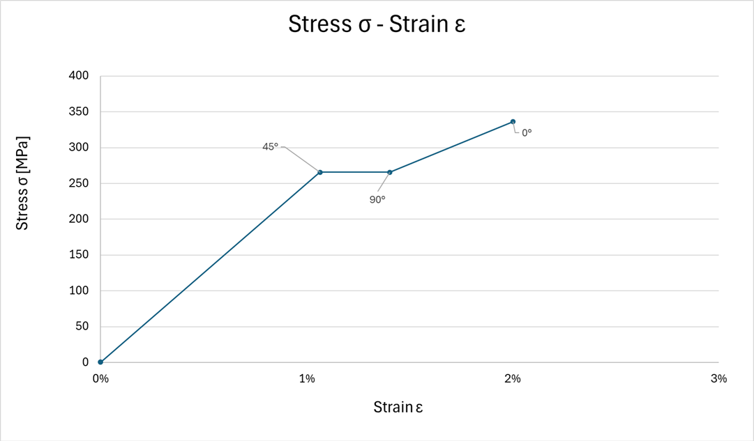
- Compression: ±45° matrix-compression → 90° matrix-compression → 0° fiber-compression; UCS ≈ 336 MPa.
- Strength ratio: UTS/UCS ≈ 1.23 (≈23% stronger in tension).
- Hashin initiation
- [0/±45/0/90]s
- UTS 413 MPa
- UCS 336 MPa
- Ratio ≈ 1.23
Rear Fuselage — Section 19 (Skin & Stringers)
Objective — Define composite skin and stringer concept, reinforcements, drop-offs, and frame joints (clips, Ø4.8 mm) for a fuselage bay between Frames A–B.
Given data
- Geometry: cylinder R = 4500 mm; frames 550 mm apart; stringer pitch 150 mm.
- Material: UD, CPT 0.184 mm.
- Skin: base 9 plies (2/4/3); reinforcement 14 plies (2/8/4), 100 × 70 mm patch.
- Stringers: h < 35 mm, R ≥ 3 mm; web 20 plies (50% 0° / 40% ±45° / 10% 90°); web = 2× flange.
- Joints: clips + Ø 4.8 mm fasteners.
What I did
- Built the master geometry (frames & stringers on skin), set pitch and feet widths.
- Mapped skin layups, drop-offs and reinforcement footprint.
- Sized stringer web/flanges and verified repairability (L1 for Ø4.8 mm).
- Defined clip joints and prepared drawings, materials list, and panel weight.


- R 4500 mm
- Pitch 150 mm
- UD CPT 0.184 mm
- Clips Ø 4.8 mm
Motorbike Rear Subframe — AlSi10Mg (SLM)
Objective — Design the lightest possible rear saddle frame within the boundary envelope, load-case compliant (static + fatigue), manufacturable by SLM (AlSi10Mg).
Process
- AM setup: AlSi10Mg; printer SLM NXG XII 600 (590 × 560 × 367 mm).
- Topology: stress-based trial (~2.8 kg) → compliance-based (~2.06 kg) with rebuilds.
- Bolts (VDI 2230): Subframe M8×4; saddle M5×4; preload & checks via hand calcs + MATLAB from FEA reactions.
- Validation (Ansys): static + fatigue, mesh conv. ~1.5 mm; local refinements near bolts.
Results
- Safety factors: > 2 static, > 1 fatigue (Goodman).
- Deflection: < 2 mm under defined loads.
- Final weight: ~656 g after combined-load map optimization.


- AlSi10Mg — SLM
- Topology-Optimized
- VDI 2230 bolts
- SF>2 / SF>1
- ~656 g
Composite drone structure
Objective — Define laminate schedule and thicknesses to minimize weight while maintaining stiffness and strength on a composite drone frame, with harmonic and impact checks on critical members.
What I did
- Selected laminate families for arms and central plate (ply angles, stacking rules, symmetry/balance).
- Ran thickness optimization under flight-load envelopes (hover, maneuver, landing).
- Built FEM and extracted harmonic response to avoid resonance near rotor frequencies.
- Performed impact scenarios on weak spots (arm-hub joints, landing edges).
Results
- Weight reduction vs baseline while keeping MS ≥ 0 in static checks.
- Minimum separation to rotor-induced frequencies achieved.
- Local reinforcements added only where needed after impact assessment.


- Layup Optimization
- Harmonic Check
- Impact FEM
- MS ≥ 0
Education

Master in Composite Materials AIRBUS Programme, Universidad Politécnica de Madrid
Courses: Design & Analysis of Advanced Composite Structures · Abaqus Lab · Space Structures.

MSc in Mechanical Engineering (Minor: Mechanical Design & Modelling) University of Bologna
Courses: Chassis & Body · Surface CAD · Structural CAD · Product Development Processes & Methods.

Erasmus+ Aerospace Engineering University of Stuttgart
Computational Dynamics (Robotics) · Computational Mechanics of Structures · Advanced FEA Technology.
BSc in Mechanical Engineering University of Bologna
Skills
Software
Soft Skills
Languages
Contact
Interested in collaborating or need the CV in a different format? Get in touch.
- Monday - Friday: 09:00 - 19:00
- Saturday: 09:00 - 19:00
- Sunday: 09:00 - 12:00